Lab 4: Digital Audio
Introduction
In this lab, we were to program a microcontrolle in C to be able to produce a square wave output on a pin and feed it into a speaker utilizing an audio amplifier to help control current. We are to use hardcoded drivers by reading the datasheet/reference sheet as a guide to write these.
Design
Reading the documentation, I decided to simply turn on and off a GPIO pin. I settled on GPIO B5, no specific reason. As for using a clock and timer, reading through the documentation, I setled on Timer 2 as I saw there were 32 bits compared to Timer 15/16. Making life easier, I decided to simply use the MSI clock as it was the default clock with every reset and I can avoid writing code to change the clock the Microcontroller would use.
Now for the calculations to get the desired frequency. This was a tough one.
Technical Documentation:
The source code can be found here: LAB4MI
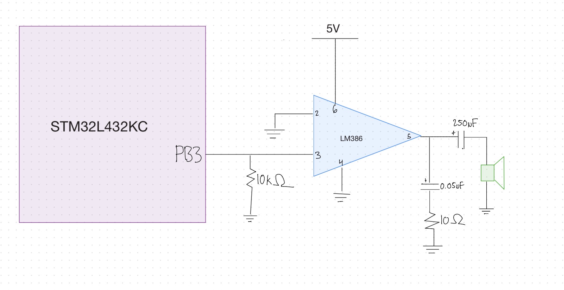
Schematic
Conclusion
Once wired up, it did play the song. It played at a reasonable temp as well. The only thing is the tempo could be off depending on the caluclations done but it still did good.AI Prototype Summary
Typing the prompt into ChatGPT, it yielded that we should use Timer2 becuase it is 32Bit. Saying that it is also one that can be configured as a toggle output. This is similar to why I chose timer2 as there were more bits to work with. I did not know however that we can configure it directly as a toggle output.
It also provided formulas that would be useful. I think the output is not as bad as it was before. It seems as it helps speed up the process of reading through the mannual. When compared to acting as HDL generator, it certainly appears to do better.