Lab 2: Multiplexed 7-Segment Display
Introduction
In this lab, we were to use time multiplexing to use the I/O on our FPGA to display two independent hexadecimal numbers on a duel seven-segment display. We had to use eight inputs to provide data and use five LEDs to display the sum of the values present on the seven segement display 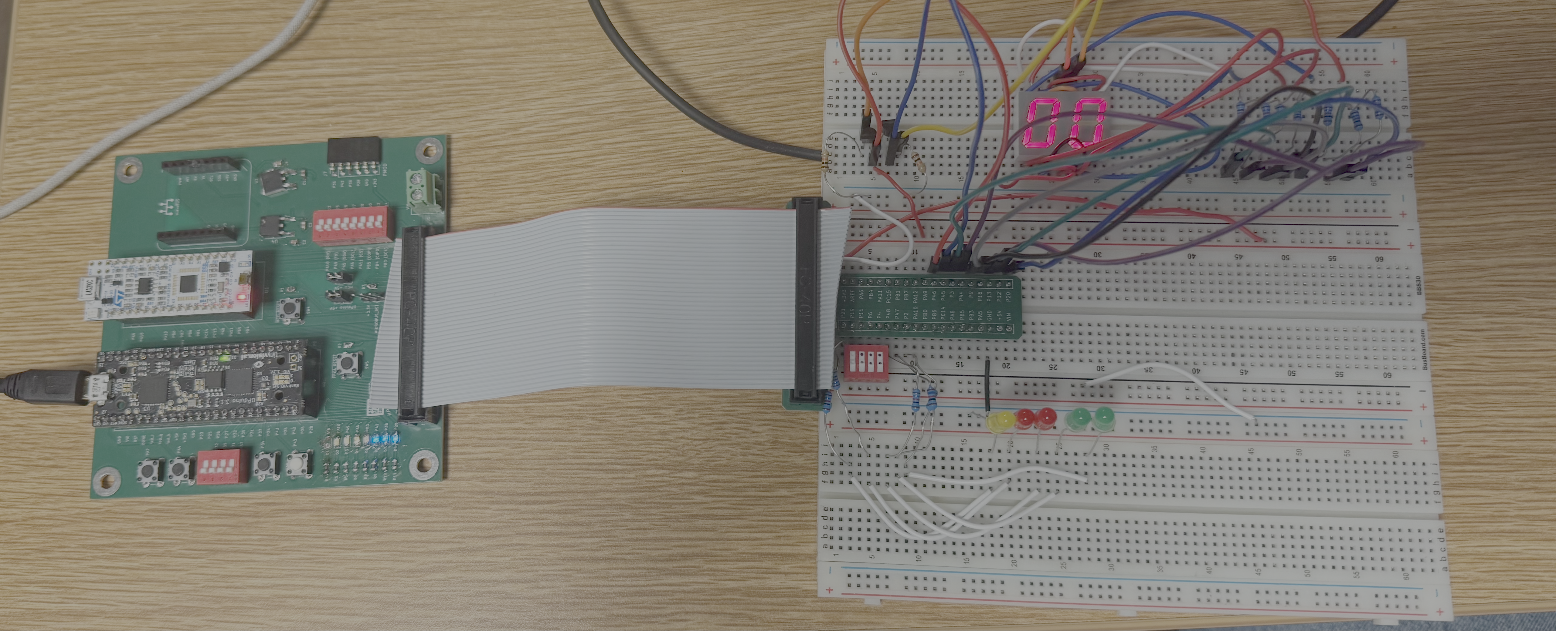
Here is the pin assignment. 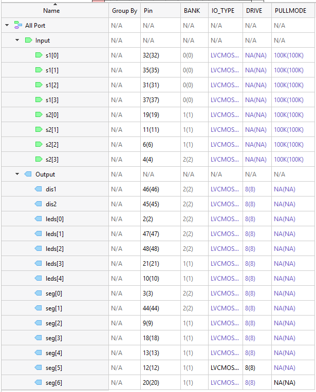
Design and Testing Methodology
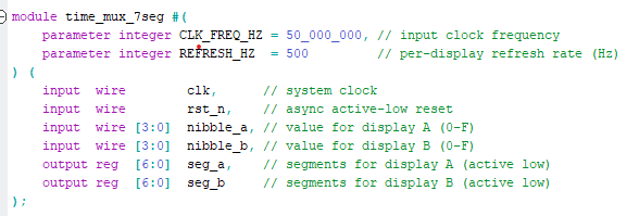
Using the on board high speed oscilator, I decided to keep track of cycles. Ideally I slow it down to 500 to 1000 HZ range as that is what the human eye can see without noticing flickering. I decided to go above 1000 Hz just in case. Utilizing the equation f_out = f_in / 2 ^ n, n being the number of bits, I deduced to using 14 bits, as it would yield a frequency of about 1.4kHz.
I decided to use seven resistors and wire each segemnt together on the same line for both 7 segment LED displays. This means that to power the corresponding segemnts on the displays, they’re joined together with a wire to minimize the amount of resistors used. Finally, linking to output GPIOs, each segment display recieved its own wire that would power the display through the transitor to help limit current.
Technical Documentation:
The source code can be found here: LAB2MBI In it, there is the testbench code used as well as the top module and sevenSegment submodule
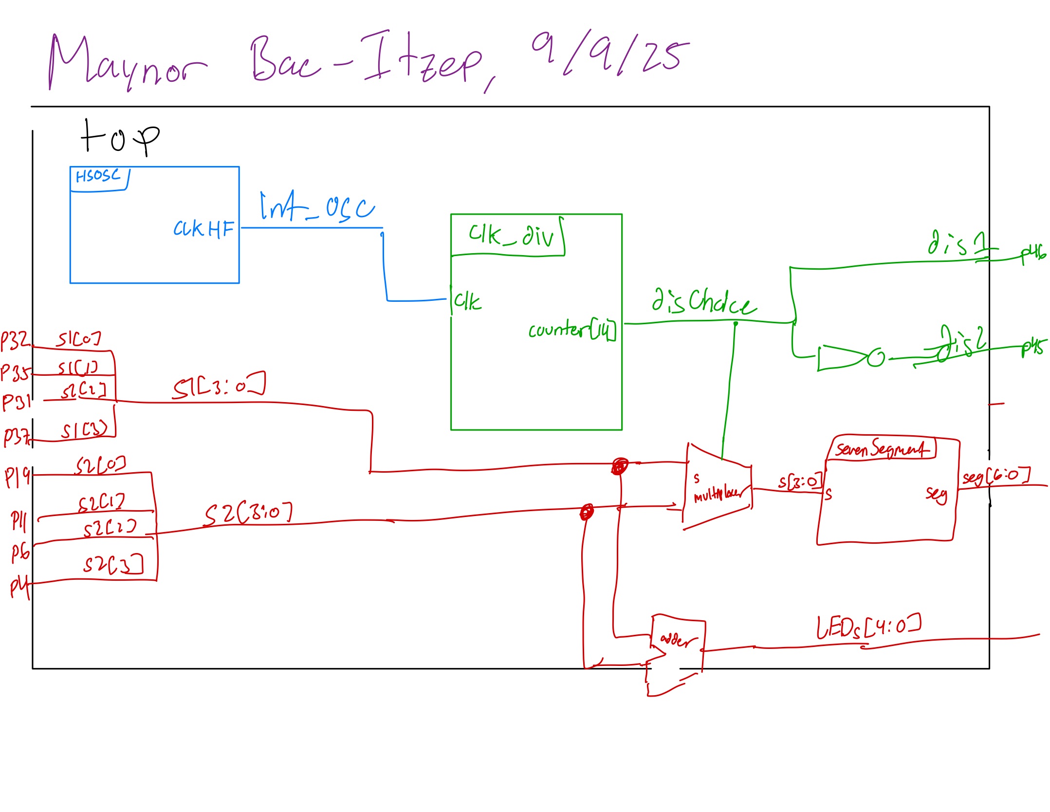
Block Diagram
The block diagram shows the overall structure of the design. There is three submodules present, the sevenSegment logic to display the correct value, the high speed oscillator block and the counter logic block.
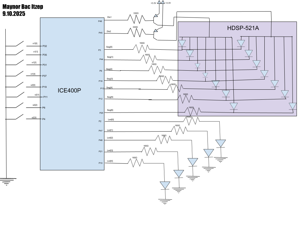
Schematic
The schematic shows the physical layout of the circut/design. The output LEDs are connected to a 160 Ohm resistor to bring down the output current of the pins. Two wires that helped power the displays were linked up to a transistors to help prevent the current exceeding the maximum output of the pins, attached to a 330 Ohm resistor to ensure when powered off, the current flows through the resistor. Finally, the segment LED themsevlevs were hooked to 160 Ohm resistors to prevent leakage and maintain stable brightness.
Results and Discussion
Starting off with the testbench, we can see the simulations ran pretty well. We can see no error wave pop up throughout the simulations. The specific vectors that were tested measured if the segment displayed the correct values for both sets of inputs while the LEDs correctly lit up the sum represented in bit form. To help clarify, this testbench utilized 21 bits, the first four being for s1 input, the next 4 for s2 input, next seven for the seg output, the next five for the LEDs, and the final bit being a variable that specifed which display was being used, 0 being for the segment for s1, 1 being for the segment for s2. Seg should display the value for the appropritate input depending on the final bit while LEDs still displayed the sum of the two inputs represented in binary. 
Conclusion
The design successfully was able to display both values given by the two sets of inputs without flickering as it swicthed between which display to power. The LEDs also correctly displayed the sum of both values in binary. I worked on this lab for about 10 hrs
AI Prototype Summary
For both outputs, the quality was not bad. HOwever, it did seem it overcomplicated the code, crafting an osc and utilizing wires for logic. I was surpised to see wires be used rather than just logic. I was surprisesd to see it compiled for the first prompt, and not utilize the oscilliator for the second prompt. My main issues with both codes is how it set two sets of seven outputs for each individual segemnt display when just one would have been enough.
For the second one, it did attempt to make its own oscilliator, but recommended to replace the ports with our own. 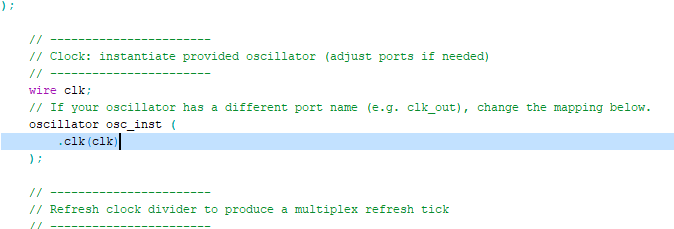 Honestly, it’s a really messy start to just prompt it like this. I think simply asking clarifying questions to help aid in the lab would suffice.