Lab 1: FPGA and MCU Setup and Testing
Introduction
In this lab, we were supposed to solder our components onto our boards. Once done, we then proceeded to code the FPGA blink three LEDS based on input recieved as well as a seven segment LED. The three LEDs has seperate conditions to be powered on: For the first LED, a XOR gate was used based on input of two switches For the second LED, an AND gate was used based on input of two switches For the third LED, it had to blink at a rate of 2.4 Hz
For the seven segement LED, it had to displace the hexadecimals 0x0 to 0xF while being able to tell the difference (EX, 8 and B are clearly different)
Design and Testing Methodology
To start, I began with the osciliator. It typically genertaes a clock signla at 24Mhz. A counter was utilized to divide the high frequency into one lower that would allow the led to blink at 2.4 Hz. It used a simple clock divider within the top module.
The next two LEDS were reletivly simple. I used gates for their respective inputs. I then assigned the result to the LED so it would flash when the conditions were met.
As for the segemnt, this was took a bit to design. I decided to utilize combinational logic and a case block to track the total inputs being provided. I have 15 different cases to track 0x1 to 0xF. With this, I decided to set 0x0 as default as no input would be provided.
Technical Documentation:
The source code for the FPGA is found in the associated. github repository
Block Diagram
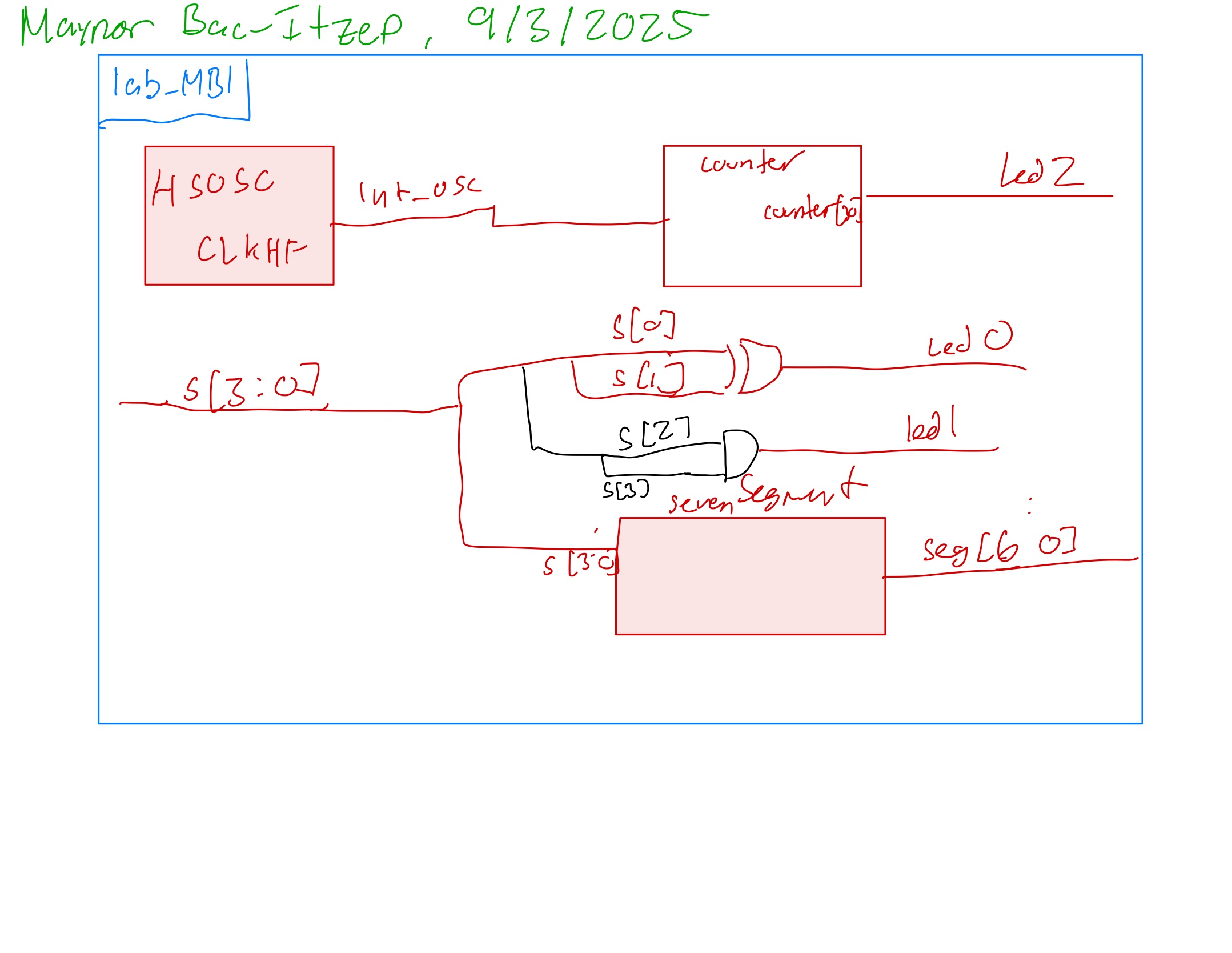 The block diagram i figure 1 demostrates the overall architecture of this design. The top-level module lab_MBI has three submodules, the high speed oscillator clock, the clock divider and the sevenSegment module.
Schematic
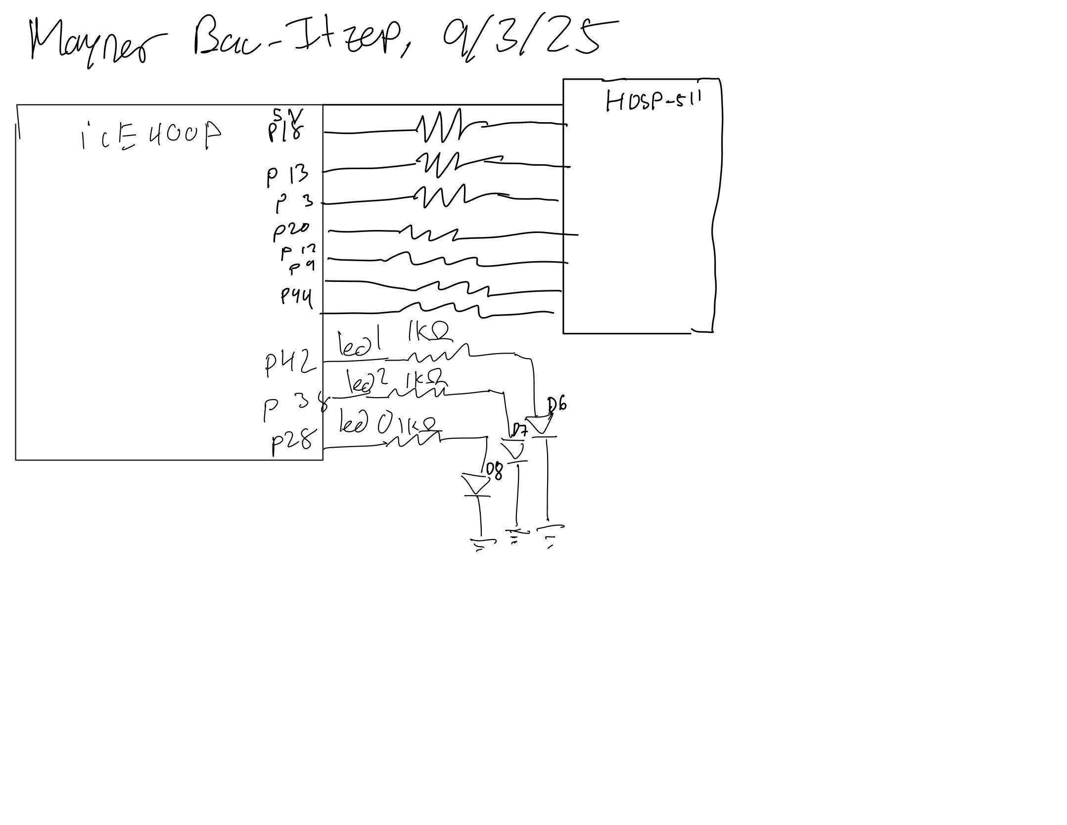 Figure 2 shows the schemqtic for the circut, highlighting the resistors values used for the LEDS.
Results and Discussion
The results was that it worked great. The seven segement LED was able to display 0x0 to 0xF.The LEDs were flashing correctly, with two being based on XOR and AND gates, the third being timed with 2.4Hz. However, I did not write out a test bench, ideally I would have written one to make sure all cases would work
Results and Discussion
The LEDs were blinking successfully and the seven segement display properly displayed the values. I spend about 16 hrs on this lab